
Turkey Light Steel Regulation 2027 Guide
Type what you need and see the answer at once.
- Published
- 17 May 2026
- Official Gazette
- No. 33256
- In force
- 1 January 2027
- Annex
- 13 sections, 125 pages
What would you like to do?
Pick one to jump to it, or scroll down and read in order.
- Read the summarySee what the regulation brings in a few numbers.
- Find my ruleSearch 135 rules by word or topic.
- Run a checkZinc coating, holes, studs, panel ratio and deflection.
- What changedTBDY 2018 and the new text side by side.
- ChecklistTick off 24 items and print them.
- FAQShort answers to the most common questions.
2027 at a glance
Short answer
The Regulation on the Design, Calculation and Construction Principles of Light Steel Buildings was published in Official Gazette No. 33256 of 17 May 2026 and comes into force on 1 January 2027. It covers prefabricated, hybrid, modular and on-site light steel buildings. In seismic design it applies in addition to the TBDY rules.
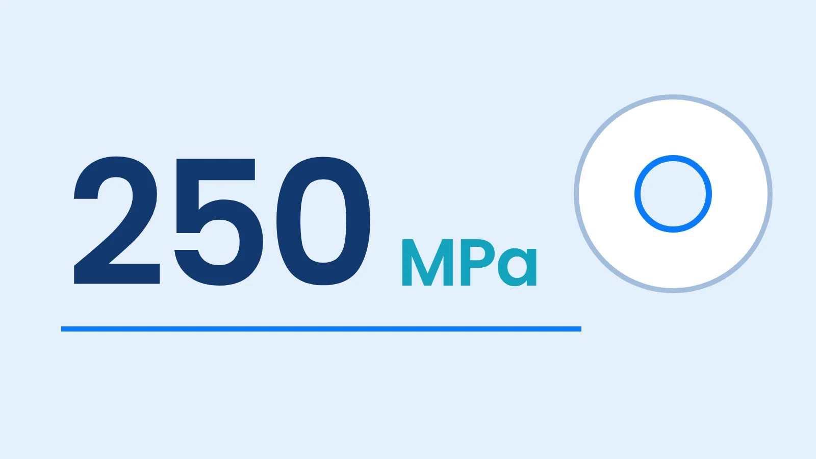
- 250 MPaMinimum yield stressTBDY 2018: 235 MPa
- 0.9 mmLoad-bearing stud thicknessTBDY 2018: 0.8 mm
- 0.40Round hole / web limitTBDY 2018: 0.70
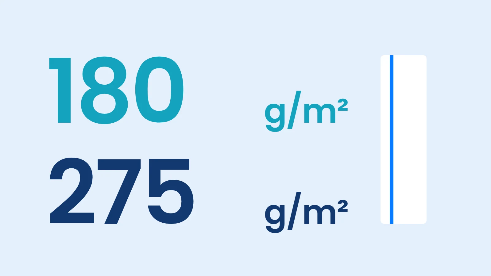
- 180–275 g/m²Zinc coating180 in 41 provinces, 275 in 40
- 14 mBuilding carried by modules onlyAbove this a rigid core is required
- 10 %Hybrid building thresholdAbove this the regulation applies
The regulation in two minutesThe eight points in the text that affect production and design the most.
Wider scope
Prefabricated, hybrid, modular and on-site profile buildings in a single text.
Higher material limit
Minimum yield 250 MPa. DX51D to DX57D are not used in load-bearing studs.
Thicker studs
At least 0.9 mm for load-bearing studs; it was 0.8 mm in TBDY 2018.
Tied to galvanizing
At least 180 g/m² in 41 provinces and at least 275 g/m² in 40.
A clear rule for bracing
Bracing is one continuous member between the top and bottom track.
Smaller holes
The circular hole diameter/web ratio dropped from 0.70 to 0.40.
Fire and modular added
Fire design, modular and hybrid systems have their own sections.
A site checklist
Temporary stability rules and an 8-heading checklist entered the text.
This page is an independent guide prepared by RENMAE. It is not the official text and does not replace legal or engineering advice. The binding text is the one published in the Official Gazette.
Rule finder
Type a word or pick a topic. Every rule shows its article and its page in the annex.
8 / 135 rules shown
- Sheet standardTS EN 10346Section 2
- Sheet thickness0.45 to 4 mmSection 2
- Minimum yield stress250 MPaSection 2 (a)
- Yield in purlins, façade girts, non-load-bearing studsMay be 220 MPaSection 2 (d)
- Tensile / yield ratioAt least 1.08Section 2 (b)
- Normal ductile materialElongation at least 10%Section 2 (c)
- High ductile materialElongation at least 16%Section 2 (c)
- Where normal ductile material may goPurlins, façade girts, non-load-bearing studsSection 2 (d)
- DX51D to DX57D steelsNot used in load-bearing studsSection 2
- Material testsResults go into the design reportSection 2 (e)
- Zinc coating, low corrosionAt least 180 g/m² (41 provinces)Annex 1
- Zinc coating, high corrosionAt least 275 g/m² (40 provinces)Annex 1
- Water, soil or industrial exposureTreated as high corrosionSection 2 (f)
- Repair of site cuts and holesZinc-rich paint, at least two coatsSection 2 (h)
- Screw testingASTM C1513 or equivalent, Table 2.1Section 2 (g)
- Screw strengthConfirmed by test and documentedSection 2 (i)
- Edge stiffener ratio0.20 ≤ c/b ≤ 0.60Section 3
- Second stiffener ratio0.10 ≤ d/b ≤ 0.30Section 3
- Below the lower ratioStiffener contribution is ignoredSection 3
- Above the upper ratioConfirmed by calculation and testSection 3
- C and Σ flange widthAt least 30 mmSection 3
- U flange widthAt least 20 mmSection 3
- Small inner bend radiusIf rp < 5t and rp < 0.1b, take rp = 0Section 3
- Ductility of mixed panelsThe lower ductility type governsSection 3
- Design methodLRFD (YDKT)Section 4.2
- Compression and bending methodEffective Width or Direct StrengthSection 4
- Basic wind speedAt least 28 m/s (100 km/h)Section 4.3
- Characteristic wind loadAt least 0.5 kN/m²Section 4.3
- Load valuesTS 498Section 4.3
- Snow and wind conditionsTS EN 1991-1-3 and TS EN 1991-1-4Section 4.3
- Notional load for stabilityNi = 0.004 YiSection 5
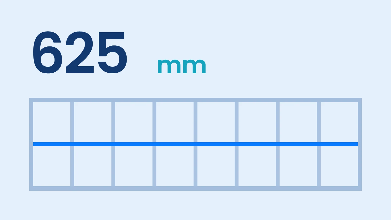
- Stud spacing for sheathingAt most 625 mmSection 6
- Load-bearing stud thicknessAt least 0.9 mmSection 6
- Load-bearing stud web depthAt least 70 mmSection 6
- Load-bearing stud sectionC or ΣSection 6
- Stud edge stiffenerAt least 9 mmSection 6
- Panel top and bottom trackU or C, at least 0.8 mmSection 6
- Buildings above 10.5 mStud demand/capacity at most 0.90Section 6
- If intermediate studs are non-load-bearingSystem counts as limited ductilitySection 6
- Segments that carry shearFull storey height segments onlySection 6
- In every load-bearing segmentHold-down at the chord studSection 6
- Width for panel contributionAt least 30 cmSection 6
- h/l for panel contributionAt most 4Section 6
- If 2 ≤ h/l ≤ 4Unit strength is multiplied by 2l/hSection 6
- Structural sheathing typesOSB, plywood, gypsum board, steel sheetSection 6
- Wall-hung cabinet loadAt least 0.5 kN/m line loadSection 6
- Behind cabinetsReinforced wall stripSection 6
- Brace layoutOne continuous member between top and bottom trackSection 6
- Brace endsFixed to tracks and to studsSection 6
- Lateral load capacityAccording to TBDY Chapter 10Section 6
- EccentricityAdditional lateral shear is calculatedSection 6
- Class of braced systemsLimited Ductility LevelSection 3
- Strap on one faceMoment T·e goes into stud designTBDY 10.4.3 (a)
- Strap connectionsFixed tautTBDY 10.4.3 (b)
- Brace tension strengthLRFD: 0.90 Ag FyTBDY 10.4.2.1 (b)
- Net sectionAnet Fu ≥ 1.20 Pn,braceTBDY 10.4.2.1 (c)
- Connected membersForces amplified by factor DTBDY 10.4.2.1 (a)
- Screw pull-out strengthNot used in seismic designTBDY 10.4.2.1 (d)
- Stud height/depth above 50At least one bridging line at mid-heightSection 6 (a)
- Bridging spacingNot more than half the panel heightTable 10.1, 5.4
- Tab lengthAt least 6dSection 6 (b)
- Edge distanceAt least 1.5dSection 6 (c)
- Screw spacingAt least 3dSection 6 (c)
- Bridging thicknessAt least 0.8 mmSection 6 (d)
- Connected flange widthAt least 3dSection 6 (e)
- Each connection pointAt least two No. 8 or larger screwsSection 6 (f)
- General deflection limitL/200Table 7.1
- Live load only deflectionL/250Table 7.1
- Infill wall or brittle finishL/300Table 7.1
- Floor on non-ductile elementsL/360Table 7.1
- Single storey drift at stud headH/300Table 7.1
- Each storey in multi-storey buildingsStorey height / 300Table 7.1
- Roof beamL/250, L/300 with brittle finishTable 7.1
- Floor natural frequencyAt least 8 HzSection 7.5
- Joist span/depthAt most 18Section 7.5
- If vibration is not metJoist spacing under 40 cm, at least two bridgesSection 7.5
- Trapezoidal deck screwsAt most 15 cm spacingSection 7.5
- Web stiffener requiredIf h/t > 180 or shear exceeds 80%Section 7.4
- Stiffener spacings ≤ 4h or s ≤ 500 mm, whichever is lessSection 7.4
- Stiffener widthAt least 2 cmSection 7.4
- Floor openingNo separate calculation up to 3%Section 7
- Above 3%Shell model, load transfer shownSection 7
- Joist bearingAt least 40 mmSection 7 (e)
- Altitude above 400 mIce load is added on roofsSection 7.6
- Screw connection resistance factorφ = 0.55Section 8.2
- Screw spacing at chord studsAt most 200 mmSection 8.2
- Screw spacing at inner studsAt most 300 mmSection 8.2
- Shear panel edge distanceAt least 10 mmSection 8.2
- Sheet connection screw lengthAt least 2t stud + 10 mm, 3 threads inSection 8.2
- Sheathing screw lengthAt least t sheathing + 2t stud + 10 mmSection 8.2
- Between screw centresAt least 3 screw diametersSection 8.2.1
- Distance to member edgeAt least 1.5 screw diametersSection 8.2.1
- Between bolt centresAt least 3 diametersSection 8.3.1
- Bolt washersWashers under head and nutSection 8.3
- Rupture checksShear, tension and block shearSection 8.4
- Foundation typeRaft or continuous footingSection 9.1
- Continuous footingsTied togetherSection 9.1
- Shear and connection anchorsTS EN ISO 898-1Section 9.2
- Number of shear anchorsEnough to transfer the shear forceSection 9.2
- Hold-down positionAligned with the end stud or corner profileSection 9.2
- Hold-downTwo-sided connectionSection 9.2
- Cast-in anchor checkTS EN 1992-4Section 9.2
- Hole positionCentred on the web axisSection 10.1 (a)
- Round hole / webdh/h < 0.40Section 10.1 (b)
- Web slenderness with holesh/t < 200Section 10.1 (c)
- Centre to centreAt least 600 mmSection 10.1 (d)
- Clear distance between holesAt least 450 mmSection 10.1 (e)
- Round hole diameterAt most 150 mmSection 10.1 (f)
- Clear distance to profile endAt least 300 mmSection 10.1 (g)
- Non-round holeAt most 65 × 115 mmSection 10.1 (h)
- Hole corner radiusrp > 2tSection 10.1 (i)
- Fabrication and erection qualityTS EN 1090-1+A1Section 10
- Dispatch to siteAfter tolerances are documentedSection 10
- Erection sequencePlanned to stay stable at every stageSection 10.2 (a)
- Before the permanent diaphragmTemporary bracing for slender panels and trussesSection 10.2 (a)
- Buckling length in temporary stateAssessed separatelySection 10.2 (b)
- Erection loadsWorkers, equipment and stored materialSection 10.2 (b)
- ChecklistTable 10.1: 8 headings, 24 itemsSection 10.3
- Fire performanceShown by test or calculationSection 11.1
- Load-bearing wall testEN 1365-1Section 11.1
- Floor and roof testTS EN 1365-2Section 11.1
- Non-load-bearing partition testTS EN 1364-1Section 11.1
- Yield factor at 500 °C0.45Table 11.1
- Connection factor at 500 °C0.55Table 11.2
- Fire protection at connectionsGreatest protection thickness is keptSection 11.4
- Building carried by modules onlyAt most 14 mSection 12.1.5
- Above 14 mRigid core requiredSection 12.1.5
- Modular structural behaviourHigh ductility levelSection 12.1.5
- Module connectionEquation 12.1.1, within elastic limitsSection 12.1.2
- Light steel share of lateral load in hybridsAbove 10% this regulation appliesSection 12.2.2
- Core connectionTrack is anchored to the core wallSection 12.2.2
- Thermal insulationTS 825, thermal break materialsSection 13.1
- WaterproofingBuilding waterproofing regulationSection 13.2
- Sound insulationBuilding noise protection regulationSection 13.3
- ServicesNo direct contact with load-bearing membersSection 13.4
Calculators
One question, one answer. Pick a tool, type a value, and the result appears at once.
Differences between TBDY 2018 and the new regulation
| Topic | TBDY 2018 Chapter 10 | 2027 regulation annex | Article |
|---|---|---|---|
| Design method | ASD (GKT) or LRFD (YDKT) | LRFD (YDKT) | Section 4.2 |
| Minimum yield stress | 235 MPa | 250 MPa; 220 MPa allowed for purlins, façade girts and non-load-bearing studs | Section 2 |
| Wall thickness range | 0.45 to 16 mm | 0.45 to 4 mm | Section 2 |
| DX51D to DX57D | No separate ban | Not used in load-bearing studs | Section 2 |
The table is our own comparison of the two texts and shows the main differences. An article that is not listed here has not necessarily stayed the same. The figures are read from the texts concerned. Verify them against the official text before making a decision.
Fabrication and erection checklist
A simplified version of Table 10.1. Tick it, print it or save it as PDF. Your ticks stay only in your own browser.
Who should do what?
The regulation does not affect everyone in the same place.
Material, profile and holes are the headings that concern you first.
- Review coil certificates against 250 MPa and the DX rule.
- Flag load-bearing stud sections under 0.9 mm.
- Check hole dimensions against the 0.40 ratio.
- Plan your galvanized stock according to the province table.
- Turn Table 10.1 into a production form.
The calculation method and the system choice are changing.
- Set up calculations with the LRFD method.
- Assess bracing layouts against the one continuous member sentence.
- Add the 0.90 ratio to the calculation template for buildings above 10.5 m.
- Add the deflection and 8 Hz checks for floors.
- Choose the fire design route at the start of the project.
The erection sequence and records are now part of the text.
- Prepare an erection sequence plan.
- Put the temporary bracing and prop arrangement in writing.
- Discuss temporary loads with the frame designer.
- Cover holes made on site with two coats of repair paint.
- Keep Table 10.1 records with the panel ID.
Decisions need to be made early.
- Plan load-bearing panels one above the other on the storeys.
- Fix the kitchen and cabinet locations before panel production.
- Check floor openings against the 3% limit.
- Make insulation and fire decisions together with the panel section.
- For projects in the transition period, clarify the governing text in writing.
Roadmap to 1 January 2027This timetable is our own suggestion. It is not in the regulation.
- This weekSee the text and its effect
- Download the annex and share it with your team.
- Compare the difference table with your own products.
- Appoint a responsible person.
- NovemberMaterial and section
- Collect the certificates.
- Update the section library.
- Check the supply of galvanizing and screws.
- DecemberDesign and form
- Update the calculation templates.
- Review the bracing and hole details.
- Prepare the inspection form.
- 1 January 2027In force
- Start new projects under the new principles.
- Clarify in writing the status of ongoing work.
- Try the form on the first project.
The regulation annex section by section
The 13 sections of the annex and the informative annexes, in plain language.
1General PrinciplesScope, related standards and design assisted by testing.
- Calculation of fatigue effects is outside the scope.
- In seismic design it applies in addition to the TBDY rules.
- The informative annexes are for information.
- Where there is no adequate calculation model, TS EN 1990 Annex D is the basis for experimental work.
2MaterialSheet, steel type, mechanical properties, galvanizing and screws.
- Flat product to TS EN 10346, 0.45 to 4 mm.
- Minimum yield 250 MPa, tensile/yield at least 1.08.
- Elongation at fracture 10% is normal ductility, 16% is high ductility.
- The requirements are checked by testing and the results are added to the design report.
3Cross-Section RequirementsDuctility class, section ratios, edge stiffener and flange width.
- With more than one panel type, the one with the lower ductility governs.
- 0.20 ≤ c/b ≤ 0.60 and 0.10 ≤ d/b ≤ 0.30.
- Flange width at least 30 mm in C and Σ, at least 20 mm in U.
4Design Principles for Structural MembersLRFD, load combinations, tension, compression, bending, shear, combined effects and buckling analysis.
- Design is carried out with the LRFD method.
- For compression and bending, the Effective Width Method or the Direct Strength Method is chosen.
- Basic wind speed cannot be less than 28 m/s, characteristic wind load not less than 0.5 kN/m².
- Section 4.11 gives how diaphragm action is modelled in frame analysis.
5Stability DesignSystem stability is provided separately for the whole structure and for each member.
- Notional loads are taken as Ni = 0.004 Yi.
- Second-order effects and geometric imperfections are considered.
- Under the stated conditions, no additional stability bracing is needed for C and Z section beams.
6Panel DesignStud, track, bracing, bridging, anchor and cabinet load.
- Stud at least 0.9 mm, web at least 70 mm, edge stiffener at least 9 mm.
- Stud spacing for sheathing at most 625 mm.
- Only full-storey-height segments carry shear.
- Bracing is placed as one continuous member.
- Hung cabinet load at least 0.5 kN/m.
7Floor DesignLoad capacity, deflection, vibration, diaphragm and connections.
- Deflection limits are in Table 7.1.
- Natural frequency at least 8 Hz, span/depth at most 18.
- Joist bearing at least 40 mm.
- Above 400 m altitude, ice load is also considered.
8Connection DesignScrewed and bolted connections, fracture limit states and screw point types.
- φ = 0.55 for screwed connections.
- Screw centres at least 3 diameters apart, at least 1.5 diameters from the edge.
- Screw spacing at most 200 mm in the chord stud, at most 300 mm in the inner stud.
- Shear fracture, tension fracture and block shear are checked.
9Foundation and Anchor DesignFoundation selection, shear anchor and hold-down.
- A raft or continuous foundation can be preferred; continuous foundations are tied together.
- Foundation design follows the TBDY principles.
- The hold-down is aligned with the end stud or corner profile and is on both sides.
- Embedded anchors are checked to TS EN 1992-4.
10Fabrication and ErectionHole rules, temporary stability and the checklist.
- Quality control is carried out to TS EN 1090-1+A1.
- Hole diameter/web below 0.40, diameter at most 150 mm.
- Until the permanent diaphragm is formed, slender panels and trusses are supported with temporary bracing.
- Table 10.1 is used for fabrication and erection checks.
11Fire DesignFire resistance by test or calculation, material and joint factors with temperature.
- Tests: EN 1365-1, TS EN 1365-2, TS EN 1364-1.
- Yield factor 0.45 at 500 °C.
- The protection thickness is maintained at joints.
12Modular and Hybrid SystemsModule joint, height limit, load sharing in hybrid buildings.
- At most 14 m in a system carried by modules alone.
- A rigid core is mandatory above that.
- In a hybrid building the limit is 10% of the lateral load.
13Principles of Insulation ApplicationInsulation related to heat, water, sound and services.
- Thermal insulation is made to TS 825; a material that provides a thermal break is used at profiles.
- Water insulation is made to the Regulation on Water Insulation in Buildings.
- For sound, the Regulation on the Protection of Buildings Against Noise applies.
- Services are placed so that they do not touch load-bearing members directly.
AnnexAnnex 1 and the Informative AnnexesCorrosion classes of the provinces, and informative annexes on design principles, floors, anchors and insulation.
- Annex 1: corrosion class of the 81 provinces.
- Informative Annex A: design principles and methods.
- Informative Annex B: floor design.
- Informative Annex C: connection anchor mechanisms.
- Informative Annex D: principles of insulation application.
The six articles of the regulation
The main text in the Official Gazette is short; the technical rules are in the annex.
- Article 1: PurposeDesign and construction of cold-formed structural members and systems, fit for use and with adequate safety.
- Article 2: ScopePrefabricated, hybrid, modular and on-site profile-built light steel buildings.
- Article 3: Legal basisPresidential Decree No. 1 on Presidential Organisation, Articles 97 and 107.
- Article 4: Applicable principlesThe annex applies. Materials follow construction products legislation. Supervision follows Laws No. 4708 or 3194. Where silent: Turkish, then European, then international standards.
- Article 5: Entry into force1 January 2027.
- Article 6: ExecutionMinister of Environment, Urbanisation and Climate Change.
Abbreviations
- TBDY
- Turkish Building Earthquake Code
- ÇYTHYE
- Turkish regulation on the design and construction of steel structures
- YDKT
- Load and Resistance Factor Design (LRFD)
- GKT
- Allowable Strength Design (ASD)
- EGY
- Effective Width Method
- DDY
- Direct Strength Method
- YYT
- Lateral load-resisting
- BYS
- Building Height Class
- R
- Response modification factor
- D
- Overstrength factor
- YDT
- Fire resistance design
Tables in the regulation
The tables people check most, as copyable text. Each links to its page in the annex.
LRFD load combinations
Section 4.3.1 · Open in annex| No | Combination |
|---|---|
| 1 | 1.4G |
| 2a | 1.2G + 1.6(Qr veya S veya R) |
| 2b | 1.2G + 1.6Q + 0.5(Qr veya S veya R) |
| 3 | 1.2G + 1.6(Qr veya S veya R) + (Q veya 0.8W) |
| 4 | 1.2G + 1.0Q + 0.5(Qr veya S veya R) + 1.6W |
| 5 | 1.2G + 1.0Q + 0.2S + 1.0E |
| 6 | 0.9G + 1.6W |
| 7 | 0.9G + 1.0E |
Self-drilling screw conditions
Table 2.1 · Open in annex| No | Diameter (mm) | Min. torque (Nm) | Surface hardness | Core hardness |
|---|---|---|---|---|
| 6 | 3.5 | 2.7 | C 50 | C 32 |
| 8 | 4.2 | 4.7 | C 50 | C 32 |
| 10 | 4.8 | 6.9 | C 50 | C 32 |
| 12 | 5.5 | 10.4 | C 50 | C 32 |
| ¼" | 6.3 | 16.9 | C 50 | C 32 |
Section ratio limits
Table 3.1 · Open in annex| Section part | Limit |
|---|---|
| Unstiffened flange | b/t < 50 |
| Flange with simple edge stiffener | b/t < 60, c/t < 50 |
| Flange with double edge stiffener | b/t < 90, c/t < 60, d/t < 50 |
| Part between two webs | b/t < 500 |
| Inclined web | hi/t < 500 sin φ, 45 < φ < 90 |
Maximum deflection limits
Table 7.1 · Open in annex| Member or use | Limit |
|---|---|
| General use (floor, beam) | L/200 |
| Under live load only | L/250 |
| Carrying infill walls or brittle finishes | L/300 |
| Floor resting on non-ductile elements | L/360 |
| Single storey: lateral drift at stud head | H/300 |
| Multi-storey: each storey | Storey height / 300 |
| Roof beam (uninsulated, not brittle) | L/250 |
| Roof beam (carrying brittle finish) | L/300 |
Characteristic bolt stress strengths
Table 8.4 · Open in annex| Bolt class | Tension Fnt (MPa) | Shear Fnv (MPa) |
|---|---|---|
| 4.6 | 300 | 180 |
| 4.8 | 300 | 180 |
| 5.6 | 375 | 225 |
| 5.8 | 375 | 225 |
| 6.8 | 450 | 270 |
| 8.8 | 600 | 360 |
| 10.9 | 750 | 450 |
Material reduction factors with temperature
Table 11.1 · Open in annex| Temperature (°C) | Yield strength | Elastic modulus |
|---|---|---|
| 100 | 1.00 | 1.00 |
| 200 | 0.98 | 0.95 |
| 300 | 0.88 | 0.83 |
| 400 | 0.68 | 0.66 |
| 500 | 0.45 | 0.48 |
| 600 | 0.28 | 0.33 |
| 700 | 0.16 | 0.21 |
| 800 | 0.09 | 0.13 |
| 900 | 0.05 | 0.08 |
| 1000 | 0.03 | 0.04 |
Connection factors with temperature
Table 11.2 · Open in annex| Temperature (°C) | Strength retention factor |
|---|---|
| 20 | 1 |
| 100 | 0.97 |
| 150 | 0.95 |
| 200 | 0.94 |
| 300 | 0.90 |
| 400 | 0.78 |
| 500 | 0.55 |
| 600 | 0.22 |
| 700 | 0.10 |
| 800 | 0.07 |
| 900 | 0.03 |
| 1000 | 0 |
Zinc coating by province
Annex 1 · Open in annexHigh corrosion, at least 275 g/m²
Adana, Amasya, Antalya, Ardahan, Artvin, Balıkesir, Bartın, Bayburt, Bilecik, Bolu, Bursa, Çanakkale, Çorum, Düzce, Edirne, Erzurum, Giresun, Gümüşhane, Hatay, İstanbul, İzmir, Karabük, Kars, Kastamonu, Kırklareli, Kocaeli, Mersin, Muğla, Ordu, Osmaniye, Rize, Sakarya, Samsun, Sinop, Tekirdağ, Tokat, Trabzon, Yalova, Yozgat, Zonguldak
Low corrosion, at least 180 g/m²
Adıyaman, Afyonkarahisar, Ağrı, Aksaray, Ankara, Aydın, Batman, Bingöl, Bitlis, Burdur, Çankırı, Denizli, Diyarbakır, Elazığ, Erzincan, Eskişehir, Gaziantep, Hakkari, Iğdır, Isparta, Kahramanmaraş, Karaman, Kayseri, Kırıkkale, Kırşehir, Kilis, Konya, Kütahya, Malatya, Manisa, Mardin, Muş, Nevşehir, Niğde, Siirt, Sivas, Şanlıurfa, Şırnak, Tunceli, Uşak, Van
Frequently asked questions
The most common questions about the 2027 regulation.

Write to us or send an email and we'll get back to you.
All contact channelsIs it the 2026 or the 2027 regulation?
It is the same regulation. It was published in the Official Gazette on 17 May 2026 and takes effect on 1 January 2027. On this site we call it the 2027 regulation, after the year it takes effect.
When does the light steel regulation come into force?
On 1 January 2027. Article 5 of the regulation gives this day as the date of entry into force.
What is the full name of the regulation?
Regulation on the Design, Calculation and Construction Principles of Light Steel Buildings. It was published in Official Gazette No. 33256 of 17 May 2026.
Which institution issued the regulation?
The Ministry of Environment, Urbanization and Climate Change. The enforcement article also names the Minister.
Which buildings does the regulation cover?
Prefabricated, hybrid, modular and on-site profile light steel buildings. Calculation of fatigue effects is outside the scope.
Does TBDY 2018 Section 10 become invalid?
The annex of the new text says that in seismic design this regulation applies in addition to the TBDY rules, and it refers to TBDY Section 10 for panel capacities. The two texts are read together.
Is there a transition period for ongoing projects?
We did not see a separate transition article in the published text. Clarify the status of your project with the project designer, building inspection and the relevant authority.
Download the regulation annex
The file was compared byte for byte with the file in the Official Gazette on 06.11.2026. For any later change, check the Official Gazette.Changes to this guide
- Guide published. The 125 pages of the regulation annex were read and compared with TBDY 2018 Section 10.
Last updated:
Cite this guide
RENMAE, "Turkey Light Steel Regulation 2027 Guide", qsteelcad.com/en/turkey-light-steel-regulation-2027, 6 November 2026.