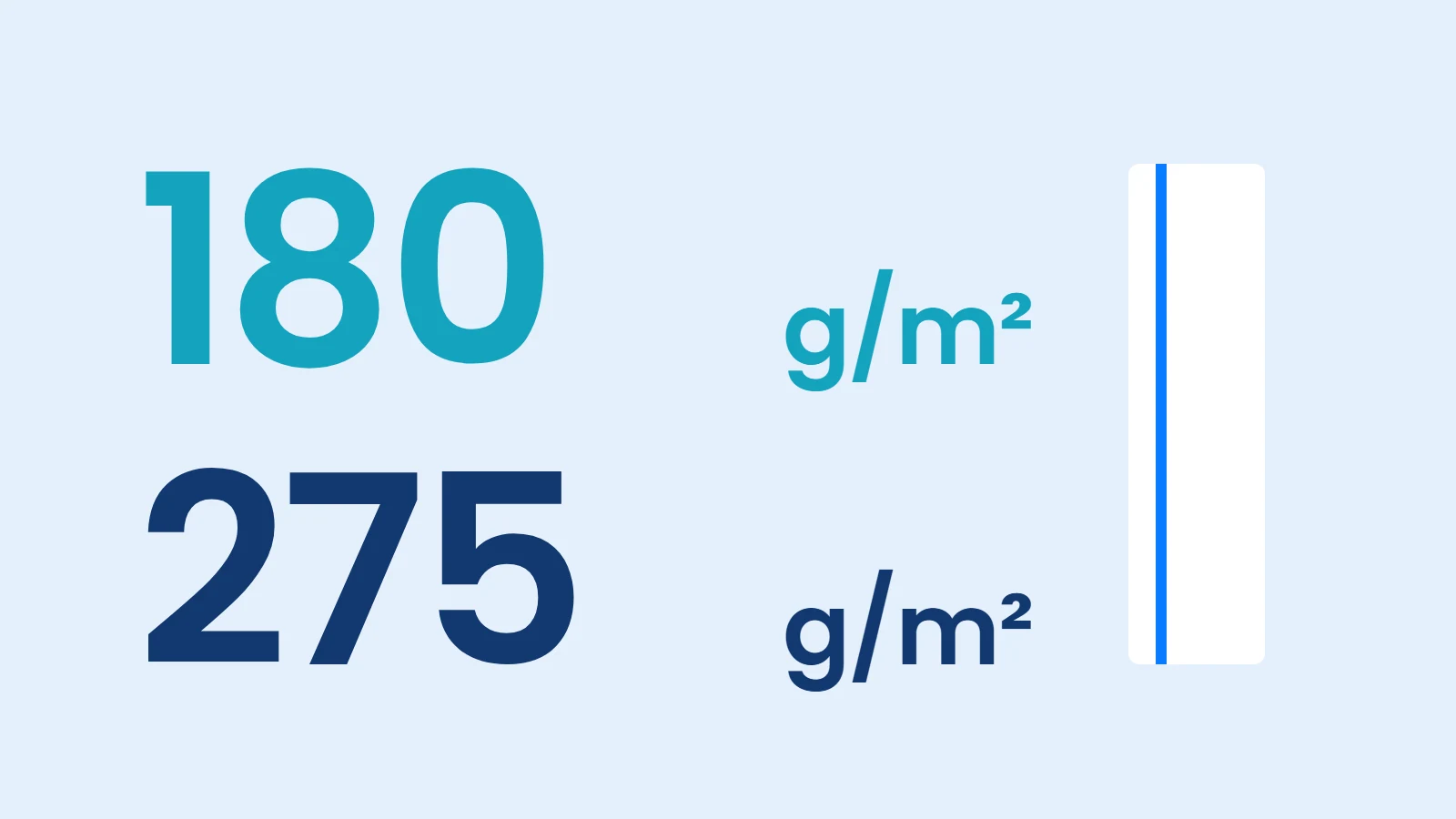

Short answer
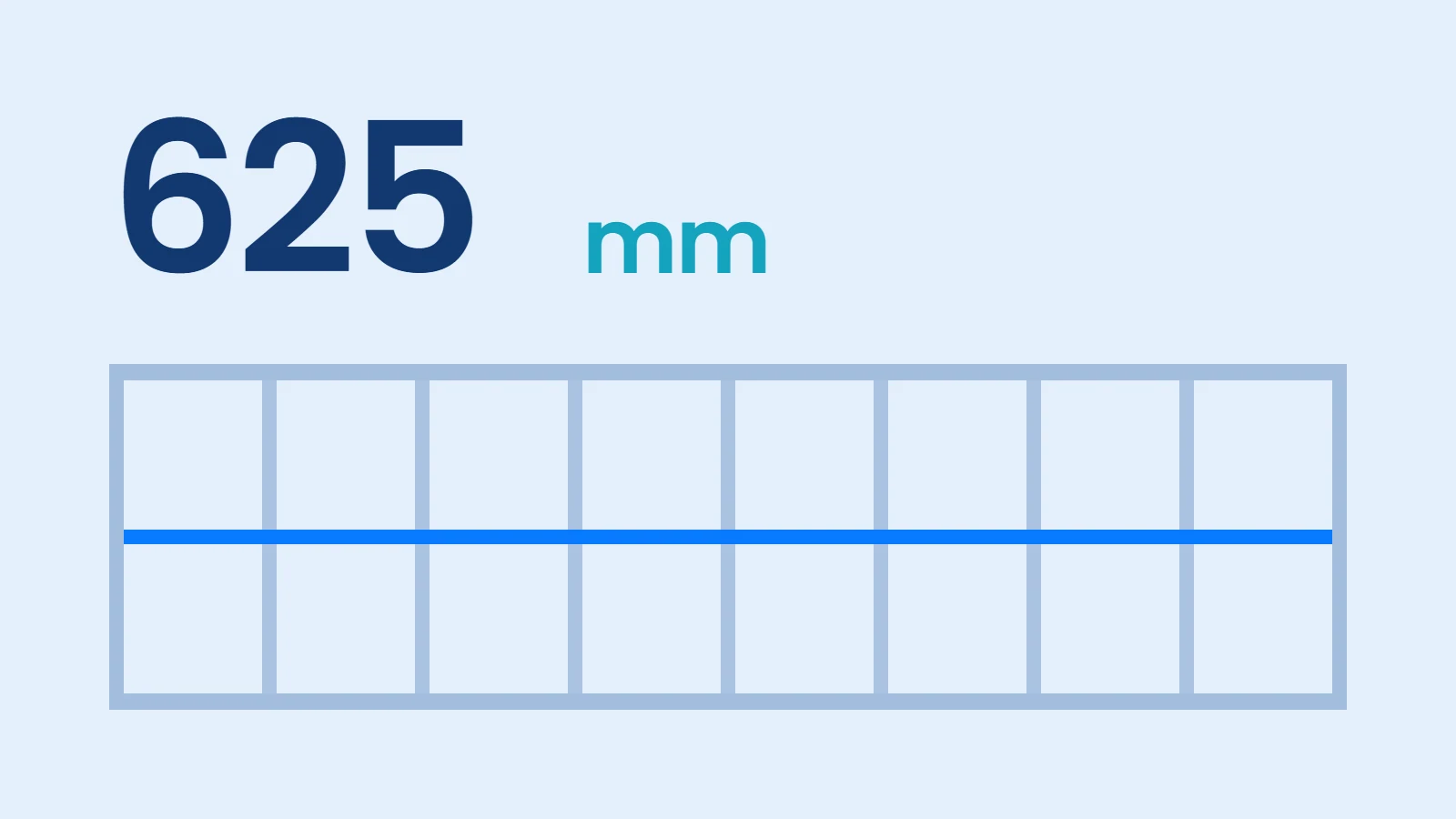
Under the 2027 regulation, a load-bearing stud is a C or Σ section at least 0.9 mm thick, with a web of at least 70 mm and edge stiffeners of at least 9 mm. Panel tracks are at least 0.8 mm. Stud spacing is at most 625 mm for load-bearing sheathing. Above 10.5 metres, stud demand/capacity is at most 0.90.
Key points
- Load-bearing stud: C or Σ, at least 0.9 mm, web at least 70 mm, edge stiffener at least 9 mm.
- Top and bottom panel track: U or C, at least 0.8 mm.
- For sheathing to count as load-bearing, stud spacing is at most 625 mm.
- Bracing is placed as one continuous member between the top and bottom track.
- Wall-hung cabinet loads are taken as a horizontal line load of at least 0.5 kN/m.
In this article
Introduction
The panel is the production unit of a light steel building. Section 6 of the regulation builds panel design on Section 4 (structural members) and Section 8 (connections); for the lateral load capacity of panels it refers to the provisions of Section 10 of the Turkish Building Earthquake Code 2018 (TBDY 2018). So the two texts work together here.
What are the minimum limits for studs and tracks?
| Member | Rule | TBDY 2018 |
|---|---|---|
| Load-bearing stud section | C or Σ | C or Σ |
| Stud wall thickness | At least 0.9 mm | At least 0.8 mm |
| Stud web height | At least 70 mm | At least 70 mm |
| Edge stiffener | At least 9 mm | At least 9 mm |
| Top and bottom panel track | U or C, at least 0.8 mm | U or C, at least 0.8 mm |
| Stud spacing for sheathing | At most 625 mm | At most 625 mm |
For studs and tracks produced outside these sections, it must be shown, by test or by analysis, that they safely carry the design load. The new text does not close this alternative route, but it puts the responsibility on the manufacturer.
What does the 10.5 metre limit mean?
If the building height is above 10.5 metres, the demand/capacity ratio in all load-bearing studs is at most 0.90. In a lower building the ratio can go up to 1, whereas in a taller building a ten percent margin is left in every stud. It is a rule that directly affects section selection as the number of storeys increases.
What if the intermediate studs are not load-bearing?
In prefabricated panel systems, if the intermediate studs are not load-bearing, these systems are treated as Limited Ductility Level. Since this sentence changes the ductility class of the system, and with it the calculation coefficients, it should be settled at the start of design.
Which panels count as load-bearing?
Only full-storey-height load-bearing panel segments are assumed to have shear capacity, and a hold-down is used at the chord studs of each segment. In the total load capacity, the contribution of panels at least 30 cm wide that satisfy h/l ≤ 4 is taken; if the ratio is between 2 and 4, the shear strength per unit length is multiplied by 2l/h.
Read nextHow doors, windows and services affect a braced panelWhat does it say about bracing?
For panels to be load-bearing under lateral load, either sheathing (OSB, plywood, gypsum board, steel sheet) or bracing members are used. Bracing members are placed as one continuous member between the top and bottom track members of the panel; their ends are connected to the stud members together with the tracks. Figure 6.4 shows this rule on a panel with X strap bracing.
The lateral load calculation is done in both directions: the lateral load acting on each storey is divided by the effective panel length on that storey and compared with the unit capacity in TBDY Section 10. The additional lateral shear forces caused by eccentricity, based on the effective panel lengths, are also calculated. If the panel system is solved with the diaphragm modelling principle of Section 4.11, the lateral load is calculated from the axial forces obtained in the bracing, and the capacity per metre is checked against these values.
What are the bridging rules?
Bridging is used to shorten the buckling length of stud members. Bridging can be connected to the stud in two ways: the end of the bridging is bent toward the stud and screwed into the section flange, or the bridging is cut to the width of its web and tabs bent toward the section flange are screwed to the stud. The geometric conditions are the same for both methods:
| Condition | Value |
|---|---|
| If height/depth ratio is greater than 50 | At least one bridging at mid-height of the profile |
| Tab length | At least 6d |
| Edge distance | At least 1.5d |
| Screw spacing | At least 3d |
| Bridging wall thickness | At least 0.8 mm |
| Width of flange connected to | At least 3d |
| Each connection point | At least two No. 8 or higher-class screws |
Here d is the characteristic diameter of the screw used. Item 5.4 of Table 10.1 also asks whether the bridging is placed at no more than half the panel height.
What does it say about cabinets and hung loads?
The text also touches on a rarely seen subject. Light steel wall panels are designed to carry the loads of fixed kitchen cabinets, wardrobes and similar fittings. At cabinet locations, a reinforced wall strip is made with an additional steel profile, a timber or OSB backing plate or a similar load-bearing arrangement. Wall-hung cabinet loads are taken as a horizontal line load of at least 0.5 kN/m, and the bending effect from the eccentricity to the stud axis is also included in the calculation.
In practice this means the kitchen plan is fixed before panel production. If the cabinet location changes later, a bending moment not accounted for in the calculation reaches the stud.
Which figures show the connection details?
Section 6 gives the typical detail of two perpendicular load-bearing walls in Figure 6.6, the corner connection in Figure 6.7 and the connection of a load-bearing wall to the floor in Figure 6.8. Profiles with alternative section geometries may also be used. These figures are examples; the connection to be used in a project is selected with its own calculation.
How are these values checked in QSteelCAD?
Stud spacing, section, bridging and bracing are built in the program from the user's panel setting. The program does not check load-bearing capacity or regulatory compliance; the user confirms that sections and spacing meet these limits. Review your section library and default panel settings before 2027.
Frequently asked
What is the minimum stud thickness in light steel?
Under the 2027 regulation, the wall thickness of a load-bearing stud is at least 0.9 mm. In TBDY 2018 this value is 0.8 mm.
What is the maximum stud spacing?
For sheathing to be accepted as load-bearing, the maximum stud spacing is 625 mm. The load calculation may require a smaller spacing.
What is the horizontal bridging spacing?
Table 10.1 asks whether bridging is placed at no more than half the panel height. For panels with strap bracing, TBDY 2018 10.4.3(d) also requires a spacing of at most h/2.
Which screws connect the bridging?
At each connection point at least two No. 8 or higher-class screws are used.
This article is general information. It does not replace project calculations, an engineer's approval or the official text. Articles and values were read from the texts in force on the article's date.