
Short answer
General purpose CAD knows lines, arcs and layers; it does not know whether a line is a stud or a lintel, or where its hole goes. Light gauge steel software keeps the model as profiles: length, section, holes and notches sit in one record. So general CAD is enough to draw a plan, but profile lists and production data are prepared by hand.
Key points
- General CAD keeps geometry; light gauge steel software keeps the part.
- The difference is not in drawing the plan but in the steps after it.
- Every manual hand-off is a step where a drawing error can reach production.
- General CAD stays a good tool for the plan, which moves across as DXF.
- Neither tool gives load-bearing approval.
In this article
Introduction
General purpose CAD and light gauge steel software can look alike on screen: both show plans, dimensions and 3D views. The real difference is out of sight. One stores the line; the other stores which part that line will be on site. This article explains where the difference appears and which jobs general CAD is still enough for.
What does general CAD do well?
General purpose CAD is a strong tool for dimensioned drawing. It is made for architectural plans, details and sheets, and it is not tied to one industry. Its strength and its limit come from the same place: a line does not know what it is. To the program, the two lines of a wall are just two lines.
What does light gauge steel software keep differently?
| Topic | General CAD | Light gauge steel software |
|---|---|---|
| Basic record | Line, arc, block | Profile: section, length, role |
| Wall | Parallel lines | Panel with studs, tracks, lintels and bracing |
| Door and window | Block | Opening that changes the inside of the panel |
| Roof | Hand-drawn section and truss | Trusses and panels built from shape, pitch and spacing |
| Holes and notches | Mark or note on the drawing | Position in millimetres from the start of the profile |
| Profile list | Prepared by hand | Comes from the model |
| Production data | Prepared by hand, entered at the machine | Written to the file the machine reads |
| Checks | Eyes and lists | Rivet hole, minimum length and clash checks before export |
| Takeoff and presentation | Prepared in separate steps | Come from the same model |
Where does the difference appear?
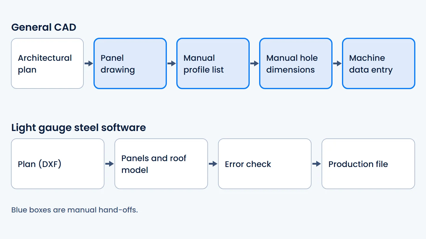
On the way from plan to machine, every manual hand-off is a step where a drawing error can reach production. In a process built on general CAD the path is usually this:
- The architectural plan is drawn.
- Panels are drawn again in general CAD.
- The profile list is made by hand.
- Hole and notch dimensions are written by hand.
- The data is entered at the machine.
In light gauge steel software the same path starts with the plan, the model is built, and the production file is written from the model. Decisions do not disappear: you still choose the section, the bracing and the roof shape. What changes is that a decision is made once and stays in the model.
Is general CAD still needed?
In most teams, yes. The architectural plan is often drawn in general purpose CAD and reaches light gauge steel software from there. The two tools do not have to replace each other: general CAD prepares the plan, and light gauge steel software turns it into parts.
Which is enough for which job?
| Situation | Sufficient tool |
|---|---|
| You only prepare architectural plans or sheets | General CAD |
| Someone else handles production and you draw concepts | General CAD |
| You send files to a rollforming line | Light gauge steel software |
| Profile lists and hole dimensions are prepared by hand | Light gauge steel software |
| You draw the same building twice, for production and for the client | Light gauge steel software |
What do both tools not do?
Neither general CAD nor light gauge steel software gives engineering approval by itself. A clash-free model does not mean a load-bearing structure. Geometry checks and structural adequacy are separate questions, and the second belongs to the project engineer.
Read nextWhy is saving bracing in CAD as a line between two points not enough?What does QSteelCAD do here?
QSteelCAD opens a plan prepared in general CAD as DXF, recognises walls, doors and windows, and builds the panels and the roof. Every profile is written to your rollforming machine file with its length and operation positions, and the file first passes rivet hole, minimum length and clash checks. Renders, takeoff and cost come from the same model. The program does not calculate load-bearing capacity; it flags joints that need approval.
Frequently asked
Can light steel panels be drawn in general CAD?
They can. But the profile list, hole and notch dimensions and machine data are prepared separately. Every manual hand-off is a step where a drawing error can reach production.
Do you still need general CAD with light gauge steel software?
In most teams, yes. The architectural plan can be drawn in general CAD and moved across as DXF; light gauge steel software turns it into panels and production data.
What is the difference between CAD and CAD/CAM?
CAD draws and models the design. CAM produces manufacturing data from that model. In light gauge steel, CAD/CAM means the profile on screen and the line sent to the machine come from the same record.
This article is general information. It does not replace project calculations, an engineer's approval or the official text. Articles and values were read from the texts in force on the article's date.