
Short answer
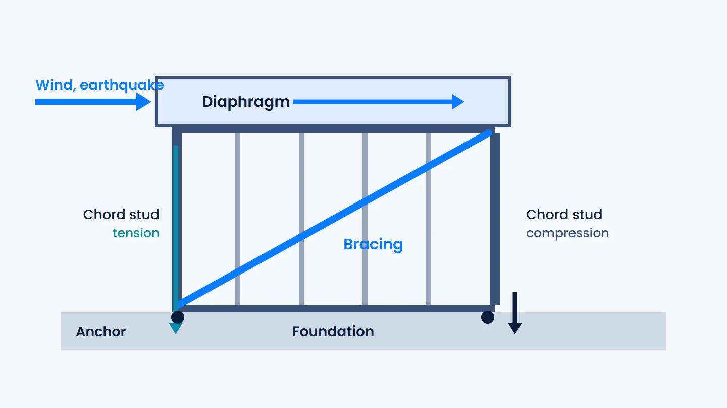
The lateral load path is the unbroken route that wind or earthquake force follows through a building. The diaphragm collects the force, tracks and collectors pass it to the panel, bracing or sheathing carries it down, and chord studs and anchors transfer it to the foundation. If a single link is missing, the system is not complete.
Key points
- The load path is a property of the chain, not of one member: the weakest link governs.
- TBDY 2018 requires load-bearing panels to be stacked one above the other on all storeys (10.2.1.4).
- Placing panels regularly and close to symmetric in plan reduces torsion.
- Members the bracing connects to are sized for forces increased by the overstrength factor D.
- Moving a panel that starts on the upper storey to a different place below is not complete until the transfer is resolved.
In this article
Introduction
A load path is the sequence of members and connections a force passes through, from where it is applied to the ground. In light steel the concept matters especially, because members are thin and connections are screwed: force passes from one part to another only if that connection is defined. Lines touching on a drawing is not enough.
Which links does lateral force pass through?
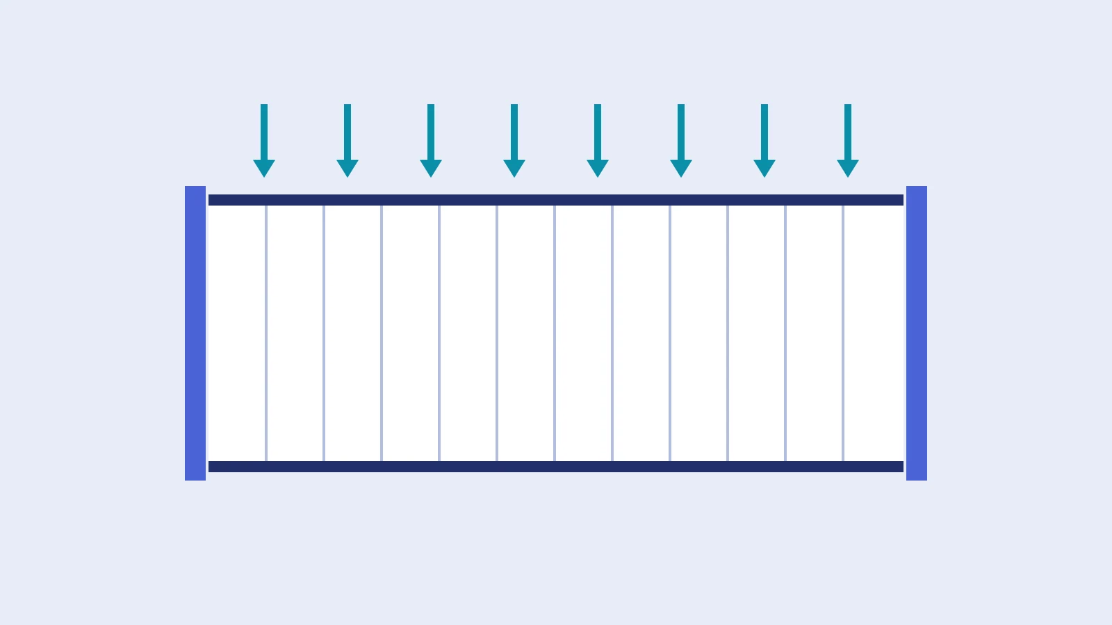
- The force arises: wind presses on the facade, an earthquake moves the mass.
- The diaphragm collects it: the roof or floor carries the force in its own plane.
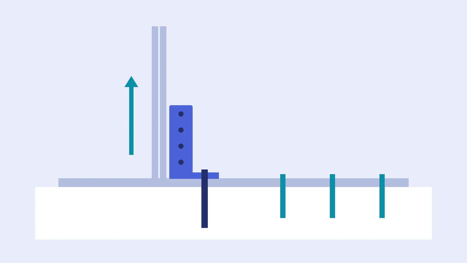
- The connection transfers it: screws and bolts pass the force to the top track of the panel.
- The panel brings it down: bracing or sheathing carries the force toward the bottom track.
- Chord studs resist overturning: tension at one end, compression at the other.
- Anchors give it to the foundation: the hold-down resists uplift, the shear anchor resists sliding.
- The foundation transfers it to the ground.
TBDY 2018 10.3 sums up this chain with three conditions: the shear capacity of the panel shall exceed the shear demand, the axial capacity of the studs shall exceed the forces acting on the stud, and the anchors shall resist the base shear, the storey shear and the overturning moment. The three conditions do not replace one another.
How does force enter the panel?
For wall bracing to take load, the force must first reach the panel. Every transition, from floor sheathing to joist, from joist to track, from track to panel, is a connection. TBDY 2018 10.5(b) requires it to be shown by calculation that diaphragm forces are safely transferred to the vertical panels, floor joists and track members with suitable connections such as screws and bolts.
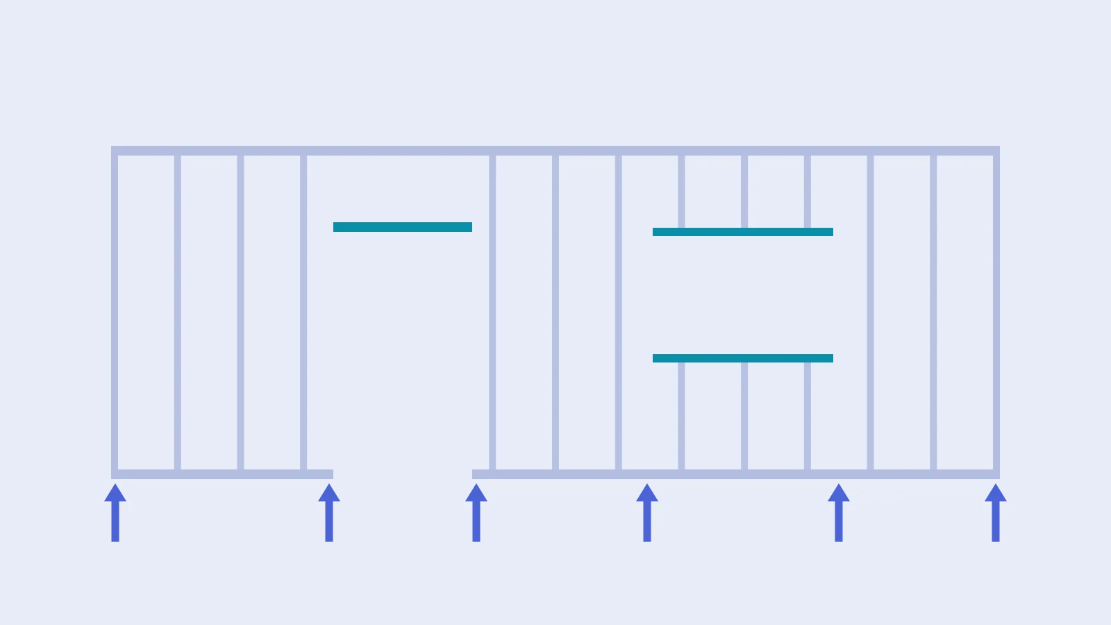
If the braced panel is only in one part of the wall, the force has to be gathered there. The member that does this is called a collector in the regulation. If a track running along the wall will take this duty, its connections and splices are resolved accordingly.
Read nextFloor and roof diaphragms: who delivers the load to the braced wall?How does force travel inside the panel?
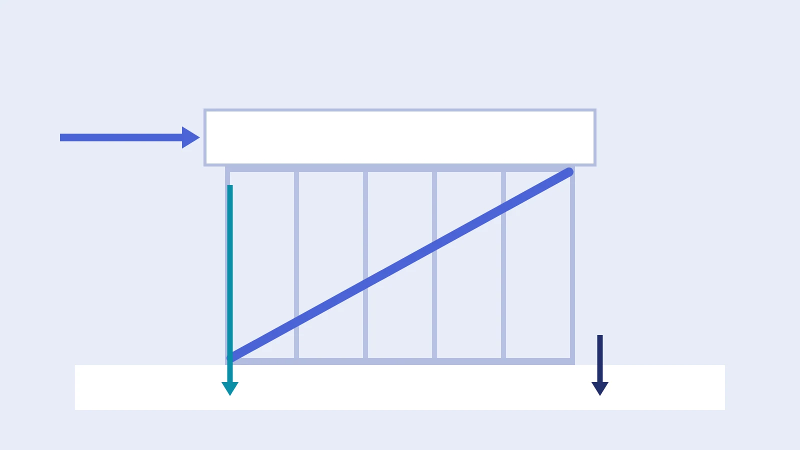
In a braced panel the force comes down along the diagonal and splits at the corner. The vertical component creates axial force in the chord stud. The horizontal component passes to the bottom track and from there to the shear anchors. In a sheathed panel the force spreads into the board through the screws and again gathers in the chord studs at the panel ends.
In both systems the chord stud works differently from an intermediate stud that carries only vertical load. In a braced panel, TBDY 2018 10.4.2.1(a) requires the forces of the chord studs, tracks and connection elements the brace attaches to be increased by the overstrength factor D. The aim is that when the brace starts to yield, the rest of the path is still standing.
How is continuity provided in a multi-storey building?
TBDY 2018 10.2.1.4 is clear: load-bearing panels are arranged one above the other on all storeys. Tension in the chord stud of an upper-storey panel must pass the floor and reach the chord stud of the panel below. This depends on the connection at floor level as much as on the alignment of the two panels.
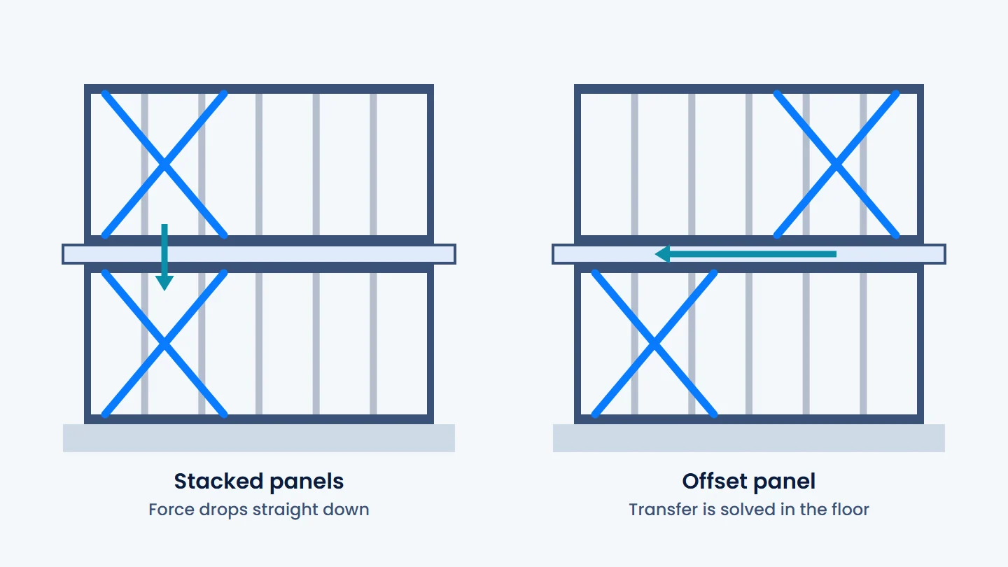
If architecture requires a braced panel to move on the lower storey, the force transfer in between becomes a separate design item. Then it is not enough for the drawing to look right only in the floor plans; the member that provides the transfer must be shown clearly.
Why does the layout in plan matter?
The same 10.2.1.4 also asks for load-bearing panels to be placed in plan as regularly as possible and symmetrically or close to symmetrically about the main axes. If panels are concentrated in one wall, the building tries to rotate under lateral load. Section 6 of the 2027 regulation requires the additional lateral shear forces arising from eccentricity to be calculated, taking effective panel lengths into account.
Where does the load path break most often?
| Break point | How it looks in the drawing | Question to ask |
|---|---|---|
| Between diaphragm and panel | Floor touches the panel, no connection is written | With which screw does the force pass to the top track? |
| Brace end | Diagonal drawn to the corner, no plate or screw group | How is the brace connected to the stud and track? |
| Chord stud | Same section as an intermediate stud | Were the brace force and vertical load checked together? |
| Panel base | Hold-down present, no shear anchor, or the reverse | Were uplift and sliding resolved separately? |
| Storey transition | Upper and lower panel on different axes | By which member is the transfer provided? |
| Opening | Window later moved next to the brace | Were the remaining panel and anchor reassessed? |
Does QSteelCAD check the load path?
No. QSteelCAD runs production-oriented checks: minimum length, clashes and model audit. The load path is an engineering assessment. The program helps with that assessment: because panels, bracing and openings sit in the same 3D model, it is easier to see the alignment between storeys, and on the roof it separately lists joints that need an engineer's approval, such as girder trusses.
Frequently asked
How is the load path shown in a drawing?
The members and connections the force passes through should be traceable in order: diaphragm connection, panel, chord stud, anchor. The detail or a reference for each link should be on the sheet.
Must a braced panel be in the same place on every storey?
TBDY 2018 10.2.1.4 requires load-bearing panels to be arranged one above the other on all storeys. A different layout requires the force transfer to be resolved separately.
Is the same load path used for wind and earthquake?
The path mostly runs through the same members, but the magnitude of the force, its distribution and the coefficients in the calculation differ. Both actions are checked separately in the project.
This article is general information. It does not replace project calculations, an engineer's approval or the official text. Articles and values were read from the texts in force on the article's date.